Flux Drive - Frequently Asked Questions
Flux Drive vs. Competing Technologies
Who are Flux Drive competitors in the adjustable flow/speed control market?
-
The most common type of flow control in the market is throttling control valves and dampers. These devices waste large amounts of energy in centrifugal applications where system power requirements vary with the cube of the pump speed / flow. The Flux Drive ASD is ultimately about saving energy by varying the drive speed and offers an elegant mechanical solution with the highest efficiencies possible without introducing damaging harmonics to motor / electrical systems.
-
Other types of speed/flow control devices are as follows: 1) fluid drives, (2) mechanical belt devices, (3) eddy current drives, and (4) electronic drives call variable frequency drives (VFDs). The major competitor of these devices in the market is the VFD; which is well developed and has also proven to have numerous operational issues and problems.
Why use a Flux Drive Adjustable Speed Drive instead of a Variable Frequency Drive?
-
Variable Frequency Drives adjust the output speed of a motor by varying the frequency of and the voltage supplied to the motor. This method of speed control has a number of drawbacks: it wastes energy by creating harmonics, it must be shielded for harmonic interference, it requires costly installation procedures, it doesn’t work well in harsh or humid environments, and it is inherently an unreliable system due to its complex nature. The Flux Drive Adjustable Speed Drive, by contrast, is a simple mechanical device that saves energy, is easy to install, and is very reliable.
What are the principal advantages of a Flux Drive over a Variable Frequency Drive (VFD)?
-
While Variable Frequency Drives are also energy saving devices, their installation and operation is not always practical or cost effective. This is due to the inherent problems in their reliability, complex electronic components, and a need for extensive infrastructure and highly trained personnel to program and service these devices. The other major problem with the VFD technology is the electronic harmonics generated by the drive which requires mitigation with additional equipment to be installed and maind. taine
The simple and reliable Flux Drive ASD is ideally suited for pump, fan and blower applications providing the energy savings of speed control without the problems often associated with VFDs. In these installations, system complexity is reduced, and vibration is eliminated and harmonic distortion problems disappear. In addition, the Flux Drive technology makes adjustable speed control available to markets previously resistant to using VFDs.
What other advantages does a Flux Drive have over a Variable Frequency Drive?
-
Additional advantages of Flux Drives over Variable Frequency Drives:
- Operates with any voltage motor without high cost upgrades like with VFDs
- No special filters and reactors required like with VFDs
- No inverter duty motor required like with a VFD
- No motor overheating at reduced pump or blower speeds
- Operates with Zero harmonic interference and no power quality issues
- No motor noise as created by harmonic (VFD) power sources
- No stray shaft currents are introduced; like by VFDs causing bearing damage
- No expensive bypass starters required like with VFDs
- Not affected by electrical disturbances or lightening
- Does not create system electrical problems (harmonics, heating, etc.)
- Eliminates nuisance dropouts that occur with VFD control/power circuits
Why does a Flux Drive have less vibration and noise than VFD?
-
A Flux Drive does not introduce Harmonics that are created by electronic (VFD) drives. As a result of the harmonics, the VFD creates audible noise and vibration in the motor. The harmonics are always present and as a result, a motor powered by a VFD needs to be upgraded to Inverter Duty rated in order to run without failing. Even with this upgrade, the noise and vibration remains and can also cause stray shaft currents that will still destroy motor bearings. By switching to a Flux Drive ASD, all these problems are eliminated.
How does the efficiency of the Flux Drive ASD compare to a VFD?
-
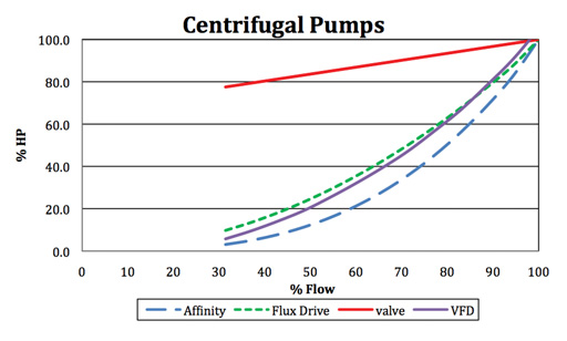
An example showing the Flux Drive ASD performance vs. a throttling valve and a VFD (at varying flow rates and horsepower) is shown below. Note that both the Flux Drive ASD and the VFD provide substantial energy savings over the Throttling Valve line, but operate with powers above the pure the Affinity curve. This is because of real world conditions that take into account the complete pumping system including the efficiencies of the Motor, Flux Drive (or VFD), Pump, and the pump system curves.
How does the efficiency of the Flux Drive ASD compare to a VFD at full power?
-
During full power/torque operation of the Flux Drive ASD and Coupling, they are designed to operate with only 1.5% slip (at 98.5% efficiency) and will produce no noticeable heat on the Induction Rotor. This highly efficient power transfer is inverse to electronic VFDs, where their losses and heat generation are a maximum at full power operations. This condition requires the VFD to provide maximum cooling at the highest power levels and results in substantial energy losses that are documented to be between 5 – 7%. In many VFD installations, climate controlled rooms are also required at a cost of additional space and power.
Are Flux Drive Couplings similar to older Hydrodynamic/Fluid Couplings?
-
YES and NO. Yes, the Flux Drive ‘soft-start’ Couplings provide soft and smooth starting to provide maximum life of the system components but do it without the potential of leaking fluids or overheating oil. Environmental concerns are no longer an issue since the Flux Drive works with only magnetic flux that is completely contained inside the magnetic can assembly and provides high efficient power transfer at 98.5%. There are no contacting surfaces to wear out and virtually no maintenance with well over a 20 year serviceable design life.
Is the Flux Drive an Eddy Current type device?
-
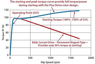
NO. The Flux Drive is an Induction device that follows AC motor theory and design. As a result, the device is ½ the size of eddy current drives (for same HP) and operates at higher efficiencies (98.5% at full power/torque). In addition and most important, the torque curve of the Flux Drive produces up to 140% torque at 100% slip (during starting). This allows the Flux Drive to start high inertia loads (i.e., conveyors, etc.) with plenty of torque available.
-
To the contrary, Eddy Current drives have a distinctive torque profile that rolls off at 100% slip and can create a ‘stall’ or slip condition that will not allow the torque to be produced and eventually overheat the eddy current drive after not being able to start (accelerate) the load shaft. (see Slip curve noted below)
-
Are Flux Drive Adjustable Speed Drives similar to older Eddy Current Drives?
-
NO. Older Eddy Current Drive technology used electromagnets that must continuously draw power to operate and create a magnetic field and develop variable torque. Those drives are also about twice as large due to being much less efficient than the Flux Drive ASD and also have a completely different torque profile/curve over the entire speed range of operation. This is the biggest and most important difference between the Flux Drive and even the newer technology permanent magnet eddy current drives.
-
All eddy current drives have torque curves that only produce about 50% of their full power/torque at a 100% slip condition (the starting event). In comparison, the Flux Drive produces 140% at start-up, thereby allowing high inertia loads (i.e., conveyors) to be started with product on the belt. This condition also allows the motor to trip off line (with standard Class 10/20 trip curves) in the event of an overload condition or load shaft seizure event.